Carson Taylor
MAKER PORTFOLIO
About
Hello! I'm a current first-year undergraduate ('27) and avid "maker." This site is dedicated to outlining my past, present, and future projects in everything I find interesting.
I'm still filling out all the details to this portfolio, so most projects don't have their own pages. I'll be continuing to work on this as time permits.
Main Projects
-
FRC 2023 Robot
-
Fully Custom CNC Router - Details WIP
-
Off-Season FRC Mini-bot - Details WIP
-
Homemade Nanoparticle Ferrofluid - Details WIP
-
Variable Hood Turret for FRC - Details WIP
1. FRC 2023 Robot -


As the Head of Design on 4131's FRC robotics team during the 2023 competition, I was tasked leading the design team to realize the team's goals and desired design features for the robot through CAD on Onshape and by producing part drawings for the hardware subteam to follow. Due to many reasons, such as team skill loss over Covid, transitioning to new CAD software, and general lack of dedicated student interest, I needed to do most of the design work myself with the majority taking place over the first three weeks of competition season. My contributions to the design fell under three main mechanisms:
-
Arm
-
Drive Base
-
Wrist

Arm Mechanism
For the 2023 competition, robots needed to quickly traverse the field to collect plastic cones and inflatable cubes, which they would deposit on a three-tiered grid of posts (for cones) and shelves (for cubes). To achieve the required reach to score game pieces on all three levels, I designed a single arm with a self-contained single-stage elevator which allowed the claw on the end to function as both an intake and scoring mechanism. While the kinematics are fairly simple, there were many constraints I had to consider to achieve an ideal design:
-
Simplicity to manufacture. Our team only had access to manual mills and lathes, a majoritarily member-ran 3D printing network, a CNC plasma cutter, and a CNC router for plastic and wood to fabricate our parts in-house. The fewer and simpler the parts, the faster the robot could be made.
-
Weight. Weight affects both the center of mass and the amount of torque required to operate the arm, therefore also affecting the maximum speed the arm can rotate without tipping the robot or overheating the motors
-
Ease of assembly. The arm should be able to be assembled within a short span of time (building off of simplicity to manufacture) and should not require a specific order of steps to do so. Mechanisms frequently take damage or break in competition and need to be able to be repaired within minutes.
-
Strength. The stronger the mechanism, the heavier and harder it is to move, but the more durable and capable it is.
-
Design complexity. The longer you can iterate on a design, the better it will eventually get. With the season's goal of having two copies of the robot, we had an abnormally compressed schedule meaning I needed to create a design quickly which could also be easily modified if design changes were needed.
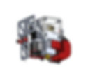
The final arm design rotated around a steel hex shaft fixed relative to the robot frame, which created a rigid structure on which a pair of large custom aluminum chain sprockets could freely spin. Two motors, which in combination with their gearboxes could drive the arm at a 240:1 gear ratio was determined to be a balance between torque and speed. Bolted between the sprockets was arm's central structure, which held a motor that drove a the arm's elevator using a chain. The elevator, driven by the chain, had two pieces of C-channel with a 40mm linear guide rail and a bearing block at the end connected to the arm, and a 2x1" box tube that could slide along the guide rail with a range of about 20". All metal parts could be cut on our low-tolerance CNC plasma cutter or machined to functionality on a mill or lathe in minimal operations. A few 3D printed components allowed for a cable chain to move along the elevator as well. A limit switch and hard stop created a resting point for the arm and served as a way to calibrate the arm's angle at the beginning of each match.

Drive Base


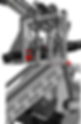
The field for the 2023 game presented two interesting design challenges for the drive base; the center of the field was entirely open, allowing for high speed movement but also aggressive defensive strategies, and a large aspect of the game was the "charge station," a large teeter-totter-style mechanism on each side of the field that robots had to scale and then collectively balance at the beginning ad end of the game for points. The team decided swerve drive, a fast and agile drive system (using four independently controlled wheels) was ideal for gameplay in the open field. However, swerve drive had difficulty getting on the charge station because of the steep angle of the ramp and because of how far into the drive base the wheels of the swerve modules had to be. I was able to counter this issue by by rotating each module 90 degrees and exposing one side, which decreased the distance from the edge of the frame to the wheel. I also shifted the bumpers so that they were as high as possible off the ground to prevent them from rubbing against the charge station ramp.
I designed the drive base to be assembled with a set of holes that aligned with a grid such that any two holes were separated by a whole number distance in either coordinate directions to reduce machining complexity and allow for designs to be more interchangeable. The majority of the frame used 2x1" box tube, which aligned with the grid and provided a strong but lightweight base to later mount the arm (light enough that steel bars had to later be added to prevent tipping from the arm's rotational inertia). Following the grid, I also designed a set of configurable brackets that I used above and below the drive base that could be plasma cut and served to connect the segments of box tube, rather than using a single belly pan to hold the drive base together, as while it required more components, it was much easier to iterate on and wasted less material than cutting a new belly pan after every change.
Following the convenience that came from using the same design the previous year, I mounted as much of the electronics as possible in a 2" space below the belly pan of the robot. To protect the wires from ground contact, I used rivnuts and button head screws to secure a polycarbonate cover plate in a way that could be easily accessible when needed. I also mounted the main battery flat and below the arm's resting point where it could be held securely but changed in a matter of seconds. Because of the pace of the design process, the rest of the robot's mechanisms had not yet been designed, so we were still considering the possibility of using pneumatics for the claw. Though they later proved unnecessary as we didn't wind up using pneumatics, I was also able to fit two pressure tanks on either side of the drive base where they would have been protected by the bumper and out of the way from the arm.
Wrist Mechanism

Due to the geometry of the cone game pieces, they could only be placed on their designated grid posts right-side up. On the field, however, they could be found in multiple orientations, including upright on the ground which the arm could pick up from the front of the robot, upright on the "substation" (an elevated platform used to add more game pieces to the field) which the arm could only reach from behind the robot, and knocked over on the ground, which the arm needed to reach down from behind the robot to grab reliably. This variety meant that the cone wouldn't always be in an upright position when it was scored. It was ultimately decided that a wrist on the end of the arm that could flip the claw 180 degrees would be the best way of approaching this problem without losing any functionality.
While the team saw the potential need for the wrist early on in the season, we considered it a low priority item because it didn't significantly limit the robot's core functionality. As a result, I waited to start until other mechanisms had been designed and sent to manufacturing before starting to work on it. Because of this, I also chose to use less-ideal components we had in the shop, instead of better-suited ones we'd have to order and test. Notably, we opted for a geared-down brushless motor rather than a 180 degree high-torque servo, and a Lazy Susan bearing which couldn't handle as much lateral load as a better-suited bearing but was stronger than a plain shaft.
My wrist design required only five custom parts, which allowed for us to quickly iterate and make spare parts. This proved vital, as we quickly found out in competition that the 3D printed components in the wrist would be the first point of failure for any hits taken by the claw. Even when our claw was entirely dismembered from a robot collision (thanks to our JV drive team) and at two or three other times during the season, we were able to fully repair or reassemble the claw wrist to a functional state before our next match, with as little as 15 minutes between our rounds. In preparation for district championships, I was able to redesign a 3D printed part of the wrist that had been a consistent point of failure to use a folded aluminum piece to reinforce the component:


